Description
S. CAMPINI REACTION PROPULSION METHOD AND PLANT Filed Aug. 30, 1932 Sheets-Sheet 1 rum J 5 S-LQMOLO CGM \ho-mulww Km F k1, m w M Dec. 17, 1935. s, AMPIN, 2,024,274
REACTION PROPULSION METHOD AND PLANT Filed Aug. 30, 1932 4 Sheets-Sheet 2 MM kw q aGI PW/ I Dec. 17, 1935. p 2,024,274
REACTION PROPULSION METHOD AND PLANT Filed A g- 30. 1932 4 Sheets-Sheet 3 Dec; 17, 1935. A N 2,024,274
REACTION PROPULSION METHOD AND PLANT Filed Aug. 30, 1932 4 Sheets-Sheet 4 Patented Dec. 17, 1935 PATENT OFFICE? REACTION-PROPULSION METHOD AND PLANT Secondo Campini, Milan, Italy Application August so, 1932, Serial No. 631,064″
I In Italy July 26, 1932 6 Claims.
The present invention is a novel reaction-propulsion method and plant, available for causing travel of the craft through air or water. The invention is based on the well known dynamic reaction principle according” to which, if a fluid under pressure is. projected or is caused to discharge through a nozzle, an impulse reaction is obtained in the opposite direction to that of the jet.
Various suggestions based on the reactionpropulsion principle have already been made designed to transform into propulsion energy the energy imparted to a gaseous or liquid fluid drawn in from’the outside and ejected in a direction contrary to that of the movement of thecraft. As regards mechanical efllciency these attempts have not met with the success hoped for, owing to the great resistances generated in the extended conduits traversed by the intaken fluid, tothe numerous deviations of direction and eddying of the fluid stream, and to inefficiency of transformation. v
The present invention supplies a complete and novel solution of the problem of reaction propulsion. It has a high efficiency and gives-high speed both for water and aircraft. In the case of watercraft, this invention minimizes ,the losses due to shocks and friction in the internal conduits and permit of carrying to the outlet, in the form of potential or pressure energy, a large portion of the kinetic or velocity energy ‘possessed by the incoming fluid. A partial recuperation of the work expended against resistance to advancement of the hull is obtainable, thus prof iting to a maximum degree from the wake of the moving craft and raising the aggregate efllciency.” In the case of aircraft the invention permits of starting, taking-off and reaching the desired altitude with reaction means possessed of great efliciency, and even permits flight at stratosphere levels with a higher efficiency than can be obtained by the means heretofore tried.
The method according to the invention consists in taking in a continuous stream of the fluid by its motion relative to the craft and prefmovement of the craft preierablyin a controlled direction in order to steer the craft.
The plant for carryingthe method’into. effect comprises at least one inlet op’ening ior taking in the fluid, preferably in close”proximity to the outer surface of the craft and preferably by the relative motion and velocity and without shocks; at least one intake conduit of substantially diverging or flare form,” but preferably of converging-diverging form for velocities higher than sound, the form being such as to permit a high efllciency of spontaneous transformation of the incoming kinetic energy into potential or pres- ,sure energy; at least one pump or compressor -during the starting period the necessary power for sucking in’the fluid and capable of driving onward the stream and increasing its spontaneous pressure-energy during normal run- 20 ning; and one or more preferably tapered outlet conduits or nozzles through which the stream is discharged substantially rearwardly’ with high reaction-propelling velocity.
The plant, in the case of air comprises, at least one thermal or combustion chamber situated immediately behind or beyond the. last compressor, this chamber beingcapable of further increasing the potential energy of the air by heating it, as by burning a liquid fuel in the air stream before the latter reaches the outlet opening.
The invention will now be described by aid of the accompanying drawings which illustrate, only by way of example, several embodiments of the invention. 1
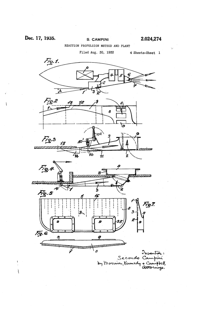
Fig. 1 shows diagrammatically the application of the device to a general form of. apparatus.
Fig. 2 is a sectional view of a special form showing an inlet opening and an inlet conduit (a 40 recuperator) in the case of an aeroplane.
Fig. 3 is a sectional view of a form showing an inlet opening and inlet conduit (recuperator) in the case of ‘a water craft.
Fig. 4 is a sectional view showing a modified form of the inlet conduit (recuperator) for water craft generally.
Figs. 5, 6 and ‘7 show in plan, front view, and section respectively a modified form of inlet opening and an inlet conduit (complete recuperstar) in the case of water craft generally.
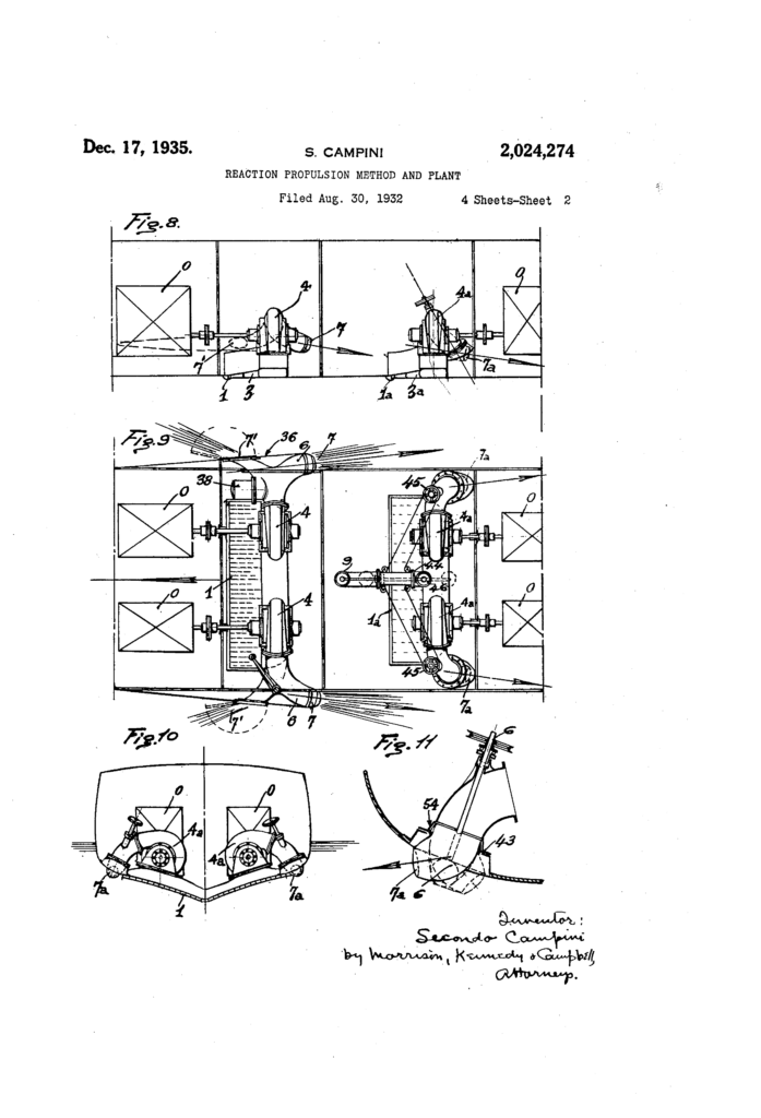
Figs, 8, 9 and 10 show in longitudinal section, plan and cross section respectively a modified installation adapted for ships of any tonnage. Fig. 11 is a sectional view of a detail relating to Figs. 9
and 10, showing the outlet conduit and opening adapted to be oriented and, serving as a rudder and for going astern.
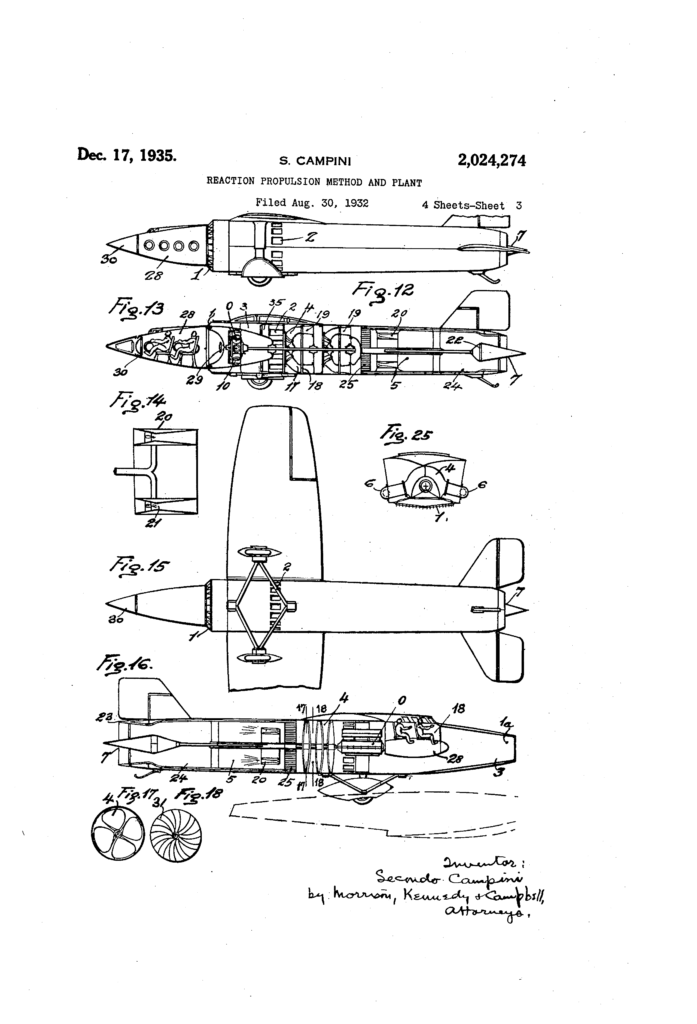
Fig. 12 is an external side elevation view of one form of a reaction aeroplane made according to the invention. Fig. 13 is a longitudinal vertical section of the aircraft shown in Fig. 12. Fig. 14 is a detail of the fuel burner shown in Fig. 13. Fig. 15 is a bottom plan of the aeroplane shown in Fig. 12.
Fig. 16 shows in vertical section a modification of the aeroplane illustrated in Figs. 12 to 15. Figs. 17 and 18 are two sections along the lines I’I-II and I8-I8 respectively in Fig. 16.
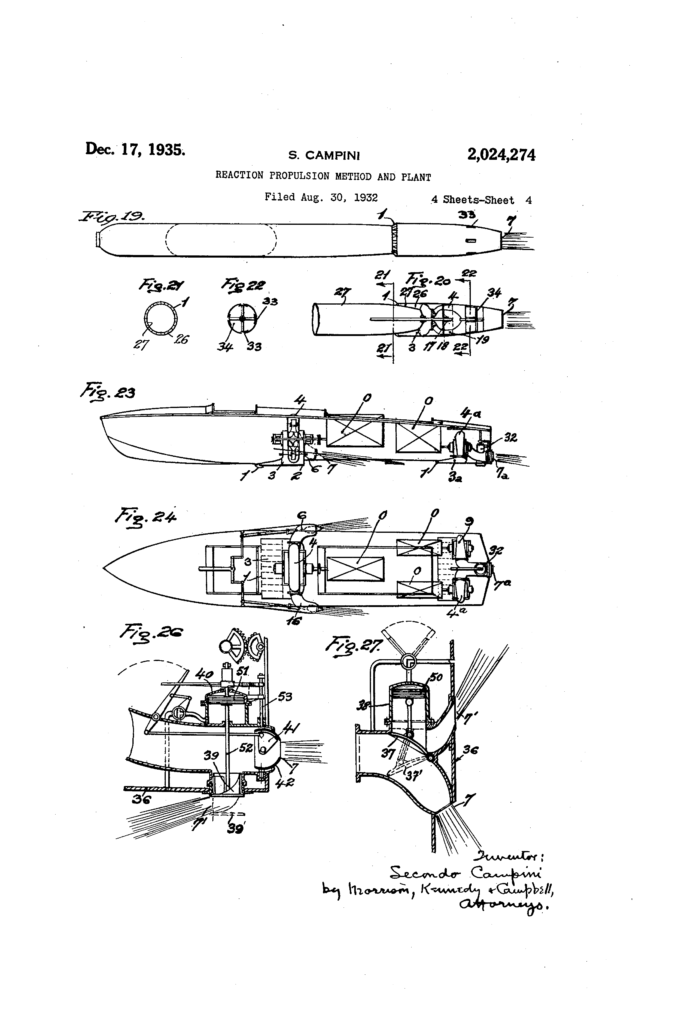
Fig. 19 illustrates in side elevation the application of the system to a torpedo, submarine, or airship, or in general to any apparatus totally immersed in the fluid. Fig. 20 is a longitudinal section of the after end portion of Fig. 19. Figs. 21 and 22 are two cross sections along the lines 2I 2I and 22-22 respectively in Fig. 20.
Fig. 23 illustrates in side elevation and vertical section the application of the invention to a motorboat. Fig. 24 is a plan of Fig. 23. Fig. 25 is a bow view of Fig. 23. Fig. 26 is a vertical section showing a detail of the outlet conduit and discharge opening at the stern of the motorboat of Fig. 23 and serving as a hydraulic rudder and for going astern.
Fig. 27 in vertical section shows a detail of the device for going astern provided in the embodiment shown in Fig. 9.
In a general way, this invention comprises the following combined elements arranged one after the other along the path of the intaken fluid stream, namely: 1) Intake opening and energy recuperator or diverging conduit; (2) suction and pressure pump or fluid drive means; (3) heating or combustion chamber with burners, not used in watercraft; and (4) outlet conduit and nozzles.
Referring to Fig. l, the fluid (air or water) enters the plant through the intake openings I and also through the automatic valves 2, during the starting of the fluid flow and when going astern; it then traverses the recuperator or diverging conduit 3 and enters the compressor 4 wherein an increase of pressure is imparted to the fluid. The compressor may be driven by an ordinary motor 0. From the compressor the fluid passes through the combustion chamber 5 and then the outlet conduit 6 passing out finally through the discharge opening or nozzle I as a jet.
The elements 3, 4, 5 and 6 are shown arranged in series one after the other relatively along the path of the fluid. In the case of water, however, the combustion chamber is omitted and the wa .ter, on leaving the pumps, flows directly to the outlet nozzles which can be oriented as above stated.
This invention is the described combination of these three or four elements. If the divergent conduit or recuperator were omitted, the propulsive effect upon watercraft would be very small; if the divergent or convergent-divergent conduit were omitted, an aircraft could not maintain its speed at high or stratosphere altitude; if on the other hand the compressor were omitted, aircraft could not overcome the starting, taking-off and rising stages by its own reaction or with a high efficiency. I now proceed to describe the successive elements of the invention in detail.
1. The recuperator.-Member 3 essentially comprises a conduit which is substantially flared or friction and eddies within the conduits) is con- 0 verted-by the transformation into pressure and, in the case of gas, by transformation into thermodynamic potential energy (temperature and pressure) that can be exploited at the subsequent outlet. Substantially, the said recuperator 15 gives the effect of a high efllciency pump or compressor in which the compression takes place spontaneously.
Different mechanical forms embodying the principle of the invention are illustrated in Figs. 2 2 to 7, in which I is the inlet projecting slightly ‘beyond the external surface of the aircraft or vessel. The said opening constitutes the inlet end of a conduit, the longitudinal axis of which follows the direction of the streamlines. Accord- 2 ingly the fluid enters by reason of the relative motion and practically without shock.
The recuperator includes the diverging conduit 8 in which the transformation of the kinetic energy into pressure energy takes place. 3 When the velocity of the advancing fluid has lowered to a value that renders motion inside of the conduit suitably slow, the fluid at recuperation pressure enters the compressor through the pressure conduit 9, the form and length of which 3 may greatly vary to suit the varying requirements of the plant.
It is advantageous to have the divergency of conduit 8 made adjustable, and also to have the free section or area of the inlet l likewise made 4 adjustable. The increase in the free section of the inlet and the decrease in the divergency are especially useful in the case of water, when the vessel is at rest or its velocity is low and the fluid instead of entering spontaneously must 4 temporarily be sucked in. Referring to Fig. 3, the portion In of the conduit 3 has its lower wall swingable, between suitable side pieces so that it can be adjusted without any loss of fluid. This portion I0 can pivot about the axis I I in order 5 simultaneously to adjust both the free section or area of the inlet and the divergency of the conduit. This movement may be controlled by a hand operated mechanism through spring rod I0 and the lever III or by an automatic device with service motor or otherwise.
Instead of adjusting the inlet opening I and the divergency of the conduit 8, provision can be made for starting and for going astern by arranging a supplementary opening or port 2 (Fig. 6 1) opening into the recuperation conduit 3 and controlled by an automatic valve 2′, which is normally closed but opens when the pressure within the conduit falls below the external pressure.
The opening 2′ may be arranged at any suitable (i point of the outer surface of the air or water craft, and is closed by the pressure itself when, c-wing to the increased velocity .of the apparatus, recuperation pressure obtains 5n the conduit exceeding the external pressure. These supplementary openings 2 are shown in Figs. 1, 2, 3, 4, 5 to 7 and others.
In Fig. 2, showing an aeroplane recuperator, the diverging conduit 8 can be altered into a converging-diverging conduit I38 fit for ve-i thin fixed walls or combs ll of suitable form are provided in front of the inlet. These combs, of which a large number are arranged parallel to the direction of motion, prevent any vegetable or other floating bodies from entering the divergent conduit and choking it. The combs may be mounted upon a plate l which may be swingably adjustable and operated from the inside at will to swing out and obstruct the inlet-opening, and so prevent it constituting a resistance to advancement when the individual propelling group to which the fluid is supplied by the inlet is not at work. A similar object is achieved by closing the’movable part III.
A type of recuperator that is most suitable when large amounts of fluid have to pass through is the one illustrated in Figs; 5 to 7. The inlet opening I isin the shape of a thin and very long slot. The extension of the inlet is the usual diverging conduit 8, which in this case is subdivided into a plurality ,of conduits by partitions IS, the object of wh’ch is to partition the fluid stream so as to avoid eddying and better to guide the fluid smoothly into the recuperation pressure collector 9, and also to firmly connect and brace the two walls of the diverging conduit itself. on the collector 9 are the connecting flanges 35 for the recuperator pumps. The center line of the inlet opening may also be other than straight. In the application of the invention to aeroplane, arships and submarines, and generally to .apparatus completely immersed in the fluid, the inlet slot may, to the betterment of efliciency, extend all round-‘the’apparatus, as will be later explained.
The invention provides suitable arrangements intended to recover the energy lost by resistance, i. e. the work of overcoming the resistance to advancement of the craft, which, brings about a,
permanent dynam’c disturbance of the fluid flowing in the vicinity of the external surface of the craft in motion. The inlet opening is therefore arranged at such a location and is of such shape that the mechanic’alefliciency of the propulsion shall be as high as possible. This is atta red by the three following arrangements:
(a) The inlet openings may advantageously have, first of ‘all, the above mentioned characteristic form of narrow slots or ports, preferably very long’and projecting very little to the outside or to the inside, so that the entering fluid shall be the fluid lying in close proximity to the hull and therefore having the least relative velocity. Besides this the slots stand open facing in such a manner that their axes shall coincide with the drection of the streamlines of the hull, so that the fluid may enter thesaid openings without any deviation or shock. In the case of water, the slots are preferably provided at the rear portion of the vessel because here the fluid has received the maximum impulse in the direction of the movement of the vessel from the impact at the bow, from the suction at the stern and from friction against the whole of the apparatus. As
a consequence, the relative inlet velocity and therefore the specific resistance to the apparatus being supplied with fluid are at a minimum, the amount of entering fluid remaining the same. This special form and the direction of the inlet openings has a great influence on’the eiliciency.
(b) The axis of the inlet conduit is preferably pressed air, preferably by burning a pulverized inclined but slightly, namely at a maximum angle A (Fig. 1), relatively’to the direction of travel of the craft, so as to minimize the component lateral to the travel-direction of the entering motion, and therefore to minimize the specific fiuid- 5 supply resistance, assuming the amount of fiuid utilized for the propulsion remains the same. In
otherwords, the axis of the first portion of the inlet conduit coincides closely with the direction of the streamline contours along the outer sur– face of the apparatus, preferably at a point where the said surface shows a great inclination relatively to the direction of the movement of the apparatus.
(0) The inlets I may be arranged in the high dynamic or over-pressure portions of the craft. and the outlet openings 1 in the under-pressure portions. V
2. The mechanical compr’essor.-After passing through the recuperator, the fluid at recuperation pressure enters the compressor or pump, which is capable of giving to the intaken fluid the further increase of pressure which is necessary in order to obtain an increased velocity at the outlet. The said compressor or pump may be an ordinary centrifugal pump 4 (Figs. 8, 9, 10, 23 and 24) or any typeof rotary or vane pump, or a helical pump or compressor (Fig. 16).
A practical characteristic of the centrifugal pump or fan which is advantageous in the case of an aeroplane or a torpedo consists (Figs. 19-20) in increasing the diametrical dimensions of the fan 4, inclusive of the right angle or flange H which compels the fluid to leave the pump in the axial direction through an opening having the form of a circular rim 18. The diifusor by which the runner is followed lies in axial direction and ‘carries the fluid to the center inlet of the next runner. Of course, instead of this compressor any other type of compressor normally in use may be employed. v
A’ characteristic of the invention is the fact. that in each plant the suction conduit of the compressor, when running normally, supplied to the compressor a positive pressure (recuperation pressure).
In the case of watercraft, the compressor is followed by the outlet conduit, orientatable’as will be set forth. 3. The heating means.-In the case of air, next after the compressor a heating or combustion chamber 5 is interposed between the compressor and the outlet conduits (Figs. 1, 13 and 16). The function of the combustion chamber is that of, raising the temperature of the advancing comfuel at constantpressure in the air.
By increasing the air temperature, the equivalent of an additional drive or compression is ob– tained the pressure however remaining thesame,
and the outlet velocity of the gas being increased, 7
so that the interposition of the combustion cham- Ber prior to the outlet is practically equivalent to the interposition of a number of centrifugal pumps, with the advantage that the increase in velocity is obtained without expenditure of me chanical pressure-power but by absorption of thermal energy. This means a saving in the load on the motors and mechanism, and permits the obtaining of extremely high outlet velocities with-‘ out excess pressure. The aeroplane at low altitude can work also without the fuel burners, with the compressor alone; however, the burners must be used at starting, and whenever an increase in the pushing effort or a power increase is desired, as for rising flight or for considerable increases in speed.
The arrangement for this purpose consists in widening the conduits into a chamber 5 through which the fluid passes. Into this chamber, preferably lined with refractory material like an oven and variable in type to suit the various shapes of the conduit, pulverized fuel is introduced, the fuel burning at once due to the high temperature that always obtains in the combustion chamber when running normally. The fuel enters through mi merous minute holes pierced in a suitable spraying burner 20, which holes in conjunction with the forward drive of the air stream assist in preventing explosions and backflring (Figs. 13, 16)
The said burner may consist (Fig. 14) in a converging-diverging conduit, advantageously of annular shape, in which the contracted or aspiration section is fitted with minute feed-holes 2|. In this manner the liquid fuel is sucked in, carried along and sprayed in the diverging conduit and then combines with the gaseous mass sur-.
rounding the burner. In starting, electric ignition is used either by spark or by incandescent wire. Also during normal running it is advisable to keep some suitable source oi?v heatinside the combustion chamber; this heat may be from an incandescent wire or from a flame supplied by ajet.
4. The outlet nozzle or discharge,The combustion chamber is followed by the outlet opening ‘1, the free area of which is preferably adjustable by means of a center spindle 22 (Fig. 13), or by some other means, for instance two or more vanes 23 (Fig. 16), the inclination of which can be varied. g
Fig. 13 shows an air reaction aeroplane in section. The air enters through theinlet openings I, traverses the diverging conduit or recuperator 3 of annular shape wherein the recuperation pressureand temperature is imparted to it, and reaches the inlet of the first runner of the compressor. During the starting period, the supplementary inlet openings 2 (fitted with valves or normally closed by a sleeve are opened either automatically or by a sliding ,or rotative motion of the internal sleeve valve 35.
A characteristic feature of this particular arrangement is the position of the pilot cabin 28 situated at the forward end of the apparatus and surrounded by the circular air inlet. The cabin is hermetically closed and can be disconnected from the aeroplane, in an emergency, from the inside (for instance by-unscrewing the handwheel 29 that keeps it pressed against a conical seat) and can then fall independently and entrain along with it a parachute suitably attached to it.
Access to the cabin 28 is had from the forward end through a manhole 30 fitted with airtight closure from the inside. Respiration inside the cabin is insured by a supply of liquid air or by an air intake provided immediately aft of the compressors, this air being then compressed to ordinary atmospheric pressure and then cooled sufflciently for breathing by external cooling pipes argiznged on the aeroplane wings or around the ca 11.
After traversing the compressors and the last axial diifusor, the air having now attained its high pressure reaches the combustion chamber 5 5 above mentioned and the hot expanded stream containing gases of combustion flows freely through the outlet conduit to the discharge opening.
The diverging inlet conduit or recuperator 10 should be of substantial length, sufficient to allow a progressive effective transformation of the velocity into recuperation pressure.
As already mentioned and as illustrated in Fig.
2, an adjustment has been provided for transforml5 ing the divergent conduit into a convergent-divergent conduit by sliding in forward direction the collar or sleeve I 2 surrounding the inlet opening and controllable from the cabin; this adjustment being advantageous when the velocity at- 20 tained reaches the velocity of sound. Other devices than the slidable sleeve may be used to serve the same purpose.
The combustion chamber 5 (Fig. 13 or 16) should be thermally insulated, especially as to 25 the portion subject to higher temperatures, either with an internal refractory lining or with an external lining consisting of a metal sheet leaving an interstice filled with air or with insulating matter; there being shown an arrangement 30 of one or more thin concentric shells 24 of refrac-. tory material leaving successive air spaces between the metal shell which carries the pressure and the inside of the chamber, so as to prevent the metal shell from becoming red hot and to per- 35 mit the attainment of high temperatures without undue heat dissipation and without weakening the parts. The said intermediate spaces should be connected to the colder portion of the combustion chamber, namely to the forward portion 40 thereof which is already under pressure but at a lower temperature. a
The adjustable outlet opening 1 beyond the converging conduit 6 may terminate in a diverging section, as shown, permitting a total or partial adiabatic expansion of the fluid being discharged. The motor 0 may be fed, for example, with compressed air or gas from the turbo-compressor 4 through suitable pipes. The motor cooling can be effected by a liquid having a high boiling point. The cooler or radiator 25 is preferably located immediately aft of the compressor sothat theheat units given up in cooling are transferred to the air serving for the propulsion, thus realizing a saving in the fuel consumption at the burners.
In Fig. 16 the embodiment in an aeroplane differs from Figs. 13-15 in the fact that the inlet opening I is circular and arranged at the extreme forward end; this intake being followed first by the diverging conduit 3 and then by the pilot cabin I8, two-runner compressor 4, impeller rings 3| (Fig. 18), combustion chamber 5 and outlet opening 7.
In the various applications of the invention, the three fundamental elements described, namely. (15 the recuperator, the turbo-compressor and the combustion chamber may show the most varied forms of embodiment, such as those described or others differing in arrangement, construction or action, according to the special requirements of T0 the apparatus concerned, the inventive principle remaining unaltered.
Thus, as a different form, Figs. 19 and 20 show the application of the system to a cigar shaped craft such as a submarine, torpedo or airship.
Here the intake I has the form of a narrow slot in the shape of a circular crown, taking in the fluid at points where Its relative inlet velocity is small. There follows the annular diverging recuperator 3, between outer and inner shells 20 and 21, in which the kinetic inlet energy is transformed into recuperation pressure. After passing through the said conduit the fluid enters the motor driven turbo-compressor 4, in which its pressure isfurther increased, and finally issues to the outside through the outlet opening I situated at the extreme stern of the apparatus. The internal inlet conduits are subdivided by radial partitions which connect the outer shell 28 to the inner shell 21.
Steering of the craft can be readily effected by means of a control device for a series of lateral supplementary slots or discharge ports 33. In Fig. 22 such a control device is shown, the.control being effected by revolving to the right or left the spokes 34 which carry the slot closing plates, thus selectively opening one or more of the slots or ports. In Fig. 21 is shown in section the annular intake I with the radial partitions already described between shells 26 and 21.
with reference to watercraft and the like, Figs. 23, 24 and 25 illustrate the application of the invention to a motor boat. In this plant, installed midway of the boats length, the water enters through the narrow inlet slot I into the kinetic energy recuperator 3 of r the type shown in Fig.3.
From the recuperator the water passes on to the centrifugal pump 4 and then to the tapered outlet conduit 6 and to the discharge opening I.’ The inlet slot is arranged at the bottom of the hull in order to utilize the greater dynamical pressure due to depth characteristic of the gliding hull.
The automatic suction valve 2 is shown, requisite duringthe starting period and while going astern; this valved port is situated at the bottom of the recuperation conduit 3.
In the rear portion of the hull, a second plant is shown in Figs. 23 and 24; and this plant may operate simultaneously with the first plant described. The recuperator 3″- is of the type illustrated in Figs. 5, 6 and ‘7, and is followed by two pumps 4* connected to a single outlet conduit ‘1 common to both pumps. The device 32 for going astern and for steering will be described further on.
Figs. 8 to 11 show an application of the system to a submarine or to a ship of any tonnage and shape. The recuperators receive the water fromat least one inlet slot I in the hull below water level; substantially it is the inlet illustrated ‘in Figs. 5, 6 and 7, bent round the hull and adapted to its shape. The inlet slots are preferably ar ranged in the rear portion of the ship. The water enters the recuperator 3 through the slots I and is led by the collector pipes 9 to the pumps 4,- from-whence it flows to the outside through the nozzles 6 and discharge openings 1, the free area of which is shown adjustable.
In Figs. 8 and 9 two plant-groups are shown, the plants comprising two pairs of pumps 4, 4 and 4, 4 symmetrically arranged. In the front or left hand unit, immediately before the outlet there such modifications as contain the described inbut can take the dotted positionll’ to cause the craft to so astern.
Fig. 26 illustrates the arrangement for going astem provided in Figs. 23 and 24 at the extreme stern of the hull; where the bottom 86 of the hull has the outlet 1′ for held withdrawn by the pistons, maymove downwards into the dotted position 88′, causing the water to be discharged through the outlet 1′ causing the craft to go astern. the outlet 1 for forward travel being p’reviomly closed by the damper I or valve 4I. Both the box 38 of outlet 1′ and the spherical cup 42 of outlet 1 may be revolved about vertical axes by rods 52, and 5; respectively, whereby the outlet nozzles I and ‘l’ and 15 the discharge jets are swung and consequently the I course of the craft is altered, either when going ahead or astern.
Fig. 11 illustrates the arrangement for reversing and going astern provided on the right hand my side of Figs. 8, 9 and 10. The nozzle 6 can revolve about an approximately vertical axis by rod or shaft 6 provision being made for water tight fitting of the nomle in its conical seat 54 in the mounting 43 of the conduit, Such swinging of 2 the nozzle brings about the alteration of the course of the craft; If the nomle be directed rearward the craft advances, but if it be swung about through 180 this causes the craft togo astern. 3
At the right side of Figs. 8 and 9, there is indicated a hydraulic control of the two symmetrical outlet nozzles so as to permit either the same or 1 an opposite revolution respectively for steering or for going astern. A piston 44 by its stroke compels the nozzle actuating sheaves to revolve in the above said opposite directions, so as to vary the resulting pushing action only or to cause reversal; whereas by rotation of the sheave 48 the steering and alteration of the course is obtained, either 40 when going ahead or when going astern.
Of course the invention is not confined to the modes of embodiment of the method and to the constructional and application formsithat have been set forth and illustrated, but comprises all -ventive principle; such variations of embodiment, therefore, though not specifically disclosed, fall within the scope of the invention.
Having now described the same is to be carried invention is: r
1. A power plant for the reaction-propulsion of aircraft comprising an intake conduit having its inlet disposed to receive a continuous stream of the surrounding air by its motion relative to the craft and the conduit being substantially flared to reduce progressively the velocity of the air stream and thereby substantially increase its pressure and potential energy, a mechanical compressorto which the intake conduit delivers the reduced-velocity air stream at such increased pressure and operating to drive onward the air stream with further increase of pressure, means beyond said compressor for further increasing the contained energy by raising the temperature out, what I claim as. my
of the air stream, and a tapered outlet conduit 1 going astern. The box 38 my invention and how 50 2. A power plant for the reaction-propulsion of aircraft comprising an intake conduit having its-inlet disposed to receive a continuous stream of the surrounding air by its motion relative to the craft and the conduit being substantially flared to reduce progressively the velocity of the air stream and thereby substantially increase its pressure and potential energy, means beyond said conduit for further increasing the contained energy by raising the temperature of the air stream, and a tapered outlet conduit or nozzle through which the stream is discharged substantially rearwardly with reaction-propelling velocity; said intake conduit having a shiitable wall occupying normally a position adjacent the intake conduit to afford a wholly flared conduit but adjustable at will to a position to provide a tapered conduit section in advance of the flared portion thereof, for super speed travel.
3. A power plant for the reaction-propulsion of aircraft comprising an intake conduit having its inlet disposed to receive a continuous stream of the surrounding air by its motion relative to the craft and the conduit being substantially flared to reduce progressively the velocity of the air stream and thereby substantially increase its pressure and potential energy, a mechanical compressor to which the intake conduit delivers the reduced-velocity air stream at such increased pressure and operating to .drive onward the air stream with further increase of pressure, and a tapered outlet conduit or nozzle through which the stream is discharged substantially rearwardly with reaction-propelling velocity; said intake conduit having a shiftable wall occupying normally a position adjacent the intake conduit to afford a wholly flared conduit but adjustable at will to a position to provide a tapered conduit section in advance of the flared portion thereof, for super speed travel.
4. A power plant for the reaction-propulsion of aircraft or watercraft comprising an intake conduit having its inlet disposed to receive a continuous stream of the surrounding air by its motion relative to the craft and the conduit being substantially flared to reduce progressively the velocity of the air stream and thereby substantially increase its pressure and potential energy, a mechanical compressor to which the intake conduit delivers the reduced-velocity air stream at such increased pressure and operating to drive onward the air stream with further increase of pressure, and a tapered outlet conduit or nozzle through which the stream is discharged substantially ,rearwardly with reaction-propelling velocity; said intake conduit being provided with a normally closed supplementary lateral inlet port adapted to be opened to admit fluid into said intake conduit to flow to said compressor and through said outlet nozzle for the purpose oi starting the normal flow of the fluid stream through the plant. 1
5. A power plant for the reaction-propulsion of aircraft or watercraft comprising an intake conduit having its inlet disposed to receive a continuous stream of the surrounding air by its motion relative to the craft and the conduit being substantially flared to reduce progressively the velocity of the air stream and thereby substantially increase its pressure and potential energy, means beyond said conduit for further increasing the contained energy by raising the temperature of the air stream, and a tapered conduit 2; or nozzle through which the stream is discharged substantially rearwardly with reaction-propelling velocity; said intake conduit being provided with a normally closed supplementary lateral inlet port adapted to be opened to admit fluid into said intake conduit to flow to and through said outlet nozzle for the purpose of starting the normal flow of the fluid stream through the plant.
6. A power plant for the reaction-propulsion of aircraft comprising an intake conduit having its inlet disposed to receive a continuous stream of the surrounding air by its motion relative to the craft and the conduit being substantially flared to reduce progressively the velocity 01 the air stream and thereby substantially increase its 3;, pressure and potential energy, a mechanical compressor to which the intake conduitdelivers the reduced-velocity air stream at such increased pressure and operating to drive onward the air stream with further increase of pressure, and a 40 lished.
SECONDO CAMPINI
________________________________________________________________
Pubblicazione gratuita di libera circolazione. Gli Autori non sono soggetti a compensi per le loro opere. Se per errore qualche testo o immagine fosse pubblicato in via inappropriata chiediamo agli Autori di segnalarci il fatto è provvederemo alla sua cancellazione dal sito
 mod.38.")


